Research Article: 2022 Vol: 21 Issue: 4S
Fault Detection of Gear Box Components Based on Fuzzy Logic Control System
Maha M.A. Lashin, Princess Nourah bint Abdulrahman University
Fadwa Alrowais, Princess Nourah bint Abdulrahman University
Fawzan S. Alfares, College of Technological Studies, PAAET
Mahdy S. Al Ajami, College of Technological Studies, PAAET
Citation Information: Lashin, M.M.A., Alrowais, F., Alfares, F.S., & Al Ajami, M.S. (2022). Fault Detection of Gear Box Components Based on Fuzzy Logic Control System. Academy of Strategic Management Journal, 21(S4), 1-12.
Abstract
Early fault detection for machine increases its life and minimizes downtime for maintenance. Type of failures and the way for faults appearing must be taken in consideration when choosing fault detection method. The machine’ failures generate periodic signals (vibration) that can be used for fault detection based on changes happened in these signals. Vibration analysis for fault diagnosis was applied for machines condition monitoring since long time. In this work, a vibration analysis is applied to investigate the state of a machine part which is widely used. The considered machinery consists of two gear boxes, motor, and water brake. Fault detection of several mechanical components in the gear boxes was investigated. The fault detection technique is based on the analysis of the vibration response. Fuzzy logic control systems were designed to predict the faults of this machinery. Hence, a code was developed by MATLAB software for calculating components’ frequencies. The technique is simple and reliable. The application of proposed technique investigates its effectiveness for increasing machine life and decreasing downtime for maintenance.
Keywords
Fault diagnostic, Vibration analysis, Fuzzy logic control system, gear boxes, Motors.
Introduction
Fault diagnosis is a wide subject that allows for a comprehensive coverage of all the areas associated with this field to be undertaken. The subject of fault diagnosis in rotating machinery is vast, including the diagnosis of items such as rotating shafts, gears, and pumps. There are different types of faults that are observed in these areas, and the methods of their diagnosis are accordingly great, including vibration analysis, model-based techniques, and statistical analysis (Less, 1998). The Data and Signal Models Methods are including Data analysis, Spectrum analysis and parametric models. Process model-based method is done by Parity equations, State observers and Parameter estimation. The more recent method is Knowledge Based Methods which mainly based on Expert systems and Fuzzy logic (Milljkovic, 2011). Vibration signals are used in predictive maintenance and machinery maintenance decisions, because changing in vibration signals related to fault can be detected by applying signal processing methods. Analyzing the vibration signal can help in early fault detection and determination of the failure type. There are three approaches of vibration signal analysis: Time domain approach, Frequency domain approach, and Time-Frequency domain approach (Kumar, 2018). Gears are an important element in the machine tool and gearboxes, and unexpected failure of it can cause economic losses. So, gearbox’ fault diagnosis based on analysis of its vibration signals can give early fault detection (Aherwar, 2017).
A dynamical model of a simple stage gearbox of electromechanical system was used to learn its pitting tooth defect by using Maximum Correlated Kurtosis Deconvolution filter combined with Spectral Kurtosis as a new approach that can be used for fault detection. The results proofed that, this technique is suitable for diagnosis and allows user to obtain better detection in the gearbox system (Ratni, 2017). The techniques that were used for diagnosis the faults of roller elements bearing include data acquisition and signal analysis techniques which are using either statistical features or artificial intelligent tools for bearing condition monitoring (Lin, 2017). A comparison between different traditional detection algorithms for detection ball bearing faults to select the suitable one explained in (Lin, 2017). The results appeared the suitability of hilbert transform and amplitude modulation algorithms for fault detection in static race more than in moving race. For diagnosis of rolling bearing fault, a new method based on vibration signal analysis using EMD (empirical mode decomposition) -SQPE (sample quantile and performance) was used. The results of using this technique revealed its ability not only in determination of different types of faults, but also in identifying the level of fault severity (Chen, 2019).
A fault diagnosis of spur gear with and without broken tooth under load was tested by using fuzzy logic control system. An automatic rule was generated for fuzzy classifier. The performance of the fuzzy inference engine was found to be 95 %, it is mean that, fuzzy control system can be used for online condition monitoring of gearbox in industries (Krishnakumari, 2017). The fuzzy logic control system for fault detection and classification on real time was used. Three phase currents, zero sequence and positive sequence current samples were considered for fault classification. The results proved that, the fuzzy logic control system can detect and classify the faults at 100 m/sec. with higher accuracy (Adhikari, 2016). A complete fuzzy logic control system implemented on separately excited DC motor for control its speed and analysis the predicted defect can be appeared in the motor. The results show fast dynamic response with minimal overshoot and negligible steady-state error (Adepoju, 2014). A fuzzy system used data coming from online fault detection and classification of transmission line. The result shows the capability of fuzzy system to right tripping action and classification of type of fault at high speed, so it can be employed in practical application (Adhikari, 2016). An automatic diagnosis system based on fuzzy logic system used for detection and classification three types of defects in rolling bearings. Using fuzzy logic. Fuzzy system results demonstrate that it is an excellent tool for identifying and classifying bearing faults (Vicente, 2001). Fuzzy Expert Systems are one of Artificial Intelligence techniques that are suitable for detection coupling defects. Compared between results of fuzzy control system and PID controller shown that the Fuzzy position controller has the best robust among represented controllers (Demidova, 2019).
In the presented work, faults of rotating machine were recognized using artificial intelligence specifically the fuzzy logic control system. Gear box, bearing, coupling and misalignment faults of water rotating machine were identified through using fuzzy logic control system. Section one covered previous studies in techniques using for diagnosis faults of rotating machines components. The water brake rotating machine is the case study used in this paper which will be explained in detail in section two. Three fuzzy logic control systems were designed through MATLAB software and were applied on frequencies of gear, bearing, and coupling for identifying their defects appear in section three. Discussion of results and conclusion of the paper come in sections four and five, respectively.
Water Brake Rotor Machine
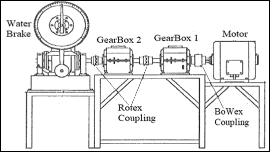
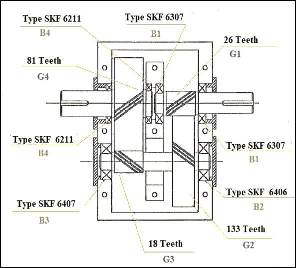
A water brake rotor machine contains electrical motor, two gear boxes, and three couplings, as shown in Figure 1 and 2 was used as an example of a machine that has different types of faults.
The internal design and specifications of the two identical gear boxes appears in Fig. 2 and Table 1.
| Table 1 Specifications and Speed of Gear Box Components |
||
|---|---|---|
| Component | Specifications | Rotating Speed |
| Electrical motor | 9 kw | 1400 r.p.m |
| Gear 1 (G1) | 26 teeth | 1400 r.p.m |
| Gear 2 (G2) | 133 teeth | 274 r.p.m |
| Gear 3 (G3) | 18 teeth | 274 r.p.m |
| Gear 4 (G4) | 81 teeth | 60 r.p.m |
| Ball bearing 1 (B1) | 6307 SKF | 1400 r.p.m |
| Ball bearing 2 (B2) | 6406 SKF | 274 r.p.m |
| Ball bearing 3 (B3) | 6407 SKF | 274 r.p.m |
| Ball bearing 4 (B4) | 6211 SKF | 60 r.p.m |
| BoWex Coupling 1 | 42 teeth | 1400 r.p.m |
| Rolex Coupling 2 | 4 teeth | 60 r.p.m |
| Rolex Coupling 3 | 4 teeth | 60 r.p.m |
The frequencies of gear box components calculated related to some formulas can be written as the following:
• Gear mesh frequency = Number of Teeth * gear shaft speed
• Coupling frequency = Number of coupling teeth * coupling shaft speed
• BPFO (outer race frequency) = (Nb/2) (1− Nb /dpcosα)
• BPFI (inner race frequency) = (Nb/2) (1+ Nb /dpcosα)
• BSF (ball base frequency) = (dp/2dp) (1−dp/dpcosα)
• FTF (fundamental train frequency) = 0.4 x r.p.m
(Nb: number of balls, dp: pitch diamert, α: contact angle).
Fuzzy Logic Control System For Gear, Bearings, Couplings, And Misalignment Defects
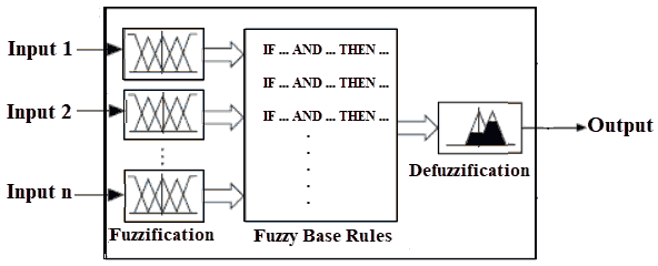
Fuzzy logic control system is based on functions Membership and their rules. Fig. 3 shows the structure of fuzzy system with fuzzication, inference, and defuzzication stages (Gougam, 2015). Fuzzification (also named fuzzy sets) means transformation of crisp into fuzzy inputs for determination rule’s truth degree. Calculating truth value of rule for concluded results of it known as inference stage. Converting crisp value that obtained on fuzzy output (fuzzy sets and degrees of membership) into crisp values done through defuzzification stage (Sivanandam, 2007).
The fuzzy-logic control system was applied in the presented work for identifying faults types that appeared in water brake rotor machine. Each component of the machine (gears, bearings, and couplings) can have fault, also the three couplings may be having misalignment (Chen, 2000; Espitia, 2019). Three fuzzy systems were designed, one for each type of fault that can be appearing in the machine. Low, medium, and high frequency ranges were entered to each fuzzy system as inputs to get fault type as output as in Fig. 4.
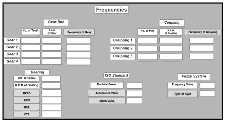
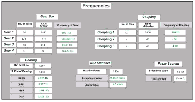
Fault type identification process was implemented through graphical user interface window which was designed by MATLAB for that purpose (Nasiruzzaman, 2010; Sharma, 2010). All specifications of machine components (speed, number of teeth, bearing serial number, number of coupling pins, and machine power) were entered to the window, as shown in Fig. 5 and 6, then components’ frequencies are calculating automatically. The identification of the fault type starts when writing any frequency’s value to get the fault type in the window. In addition, the ISO standard for vibration accepts or alarm levels appeared in the window as in Fig. 6 and the output will be the fault type.
Fuzzy System for Gear Fault
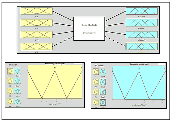
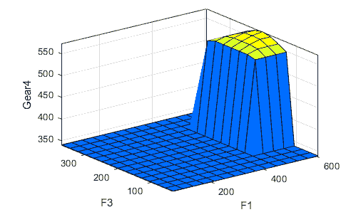
A fuzzy system was designed for gears of gear box to determine the faults that may be appear at any one of them. The gear fuzzy system has three inputs and outputs as in Fig. 7(a), the inputs as in Fig. 7(b) are the different frequencies of all gears of gear box (F1, F2, F3, and F4), the outputs are the type of fault that can appears in the gears (Gear1, Gear2, Gear3, and Gear4) as shown in Fig. 7(c). Low, medium, and high frequencies ranges of gear fuzzy system inputs are presented in Table 2. If-Then rules used as a part of proposed fuzzy control or Fuzzy decision step. Table 3 shows some of the fuzzy rules that implemented in F1, F2, F3 and F4 at the four types of gears fault Gear1, Gear2, Gear3, and Gear4. Faults can be found in the three gears depending on each input’ frequency value. Table 4 and Fig. 8 explain the range of frequencies for each gear that has defect and output of the gear fuzzy system, respectively.
| Table 2 Levels Of Gear Fuzzy Systems Inputs Values |
|||
|---|---|---|---|
| Input Variables | Low | Medium | High |
| F1 | 1 - 200.8 | 200 - 450.2 | 449.7 - 828 |
| F2 | 8 - 26.94 | 27.11 - 61.79 | 61 - 112.5 |
| F3 | 35 - 119.6 | 119 - 280.5 | 280 - 502.7 |
| F4 | 1 – 142 | 146 - 416 | 410 - 650 |
| Table 3 Some of gear fuzzy systems rules |
|---|
| Fuzzy Rules (If-Then rules) – relationship between inputs and output |
| If (F1 is M) and (F2 is L) and (F3 is L) and (F4 is L) then (Gear1 is G1M) (Gear2 is G2L) (Gear3 is G3L) (Gear4 is L) (1) |
| If (F1 is L) and (F2 is L) and (F3 is M) and (F4 is H) then (Gear1 is G1L) (Gear2 is G2L) (Gear3 is G3M) (Gear4 is M) (1) |
| If (F1 is H) and (F2 is M) and (F3 is M) and (F4 is M) then (Gear1 is G1M) (Gear2 is G2_H) (Gear3 is G3H) (Gear4 is H) (1) |
| If (F1 is H) and (F2 is M) and (F3 is M) and (F4 is H) then (Gear1 is G1M) (Gear2 is G2M) (Gear3 is G3M) (Gear4 is M) (1) |
| If (F1 is M) and (F2 is M) and (F3 is H) and (F4 is H) then (Gear1 is G1H) (Gear2 is G2_H) (Gear3 is G3M) (Gear4 is M) (1) |
| If (F1 is M) and (F2 is L) and (F3 is H) and (F4 is H) then (Gear1 is G1H) (Gear2 is G2M) (Gear3 is G3M) (Gear4 is M) (1) |
| Table 4 Gear Fuzzy System Inputs and Outputs |
||||||||
|---|---|---|---|---|---|---|---|---|
| Variable | Inputs (frequencies rang e) | Outputs (gear has fault) | ||||||
| F1 (Hz) | F2 (Hz) | F3 (Hz) | F4 (Hz) | Gear1 | Gear2 | Gear3 | Gear4 | |
| Values | 575.63 | 67.2 | 35 | 502.133 | Gear number 1 has defect | -------- | -------- | -------- |
| 432.51 | 74.113 | 35 | 496.12 | -------- | Gear number 2 has defect | -------- | -------- | |
| 4532.211 | 69.332 | 78.215 | 595.43 | -------- | -------- | Gear number 3 has defect | -------- | |
| 399.51 | 59.611 | 34.12 | 606.12 | -------- | -------- | -------- | Gear number 4 has defect | |
Fuzzy System for Bearing Faults
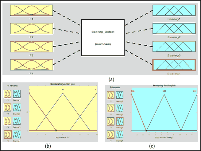
A fuzzy system was designed for bearing of gear box to determine the faults that may be appear at any one of them. The bearing fuzzy system have three inputs and outputs as in Fig. 9 (a), the inputs as in Figure 9(b) are the different frequencies of all bearings of gear box (F1, F2, F3, and F4) the outputs are the type of fault that can appears at any bearing of gear box (Bearing 1, Bearing 2, Bearing 3, and Bearing 4) as shown in Figure 9(c).
Figure 9: (A) Bearing Fuzzy System, (B) Inputs of Bearing Fuzzy System, (C) Outputs of Bearing Fuzzy System
| Table 5 Levels Of Bearing Fuzzy Systems Inputs Values |
|||
|---|---|---|---|
| Input Variables | Low | Medium | High |
| F1 | 0.03 - 0.9829 | 0.983 - 4.492 | 4.492 - 8.39 |
| F2 | 1 – 31.38 | 30.38 –157.6 | 158 -282 |
| F3 | 2 - 28.58 | 30.3 - 137.8 | 140.8 - 279 |
| F4 | 0.1 - 6.46 | 1.69 -14.41 | 9.64 - 22.36 |
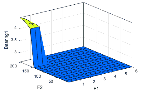
Values of input variables to bearing fuzzy system have three levels: low, medium and high frequencies values as shown in Table 5. If-Then rules were used as a part of the proposed fuzzy control or Fuzzy decision step. Table 6 shows some of the fuzzy rules that were implemented in F1, F2, F3, and F4 to get which bearing has defect. Faults can be found in bearings depending on each input’ frequency value. Table 7 and Figure 10 explain the range of frequencies for each bearing of gear box that has defect and the output from bearing fuzzy system, respectively.
| Table 6 Some Of Bearing Fuzzy Systems Rules |
|---|
| Fuzzy Rules (If-Then rules) – relationship between inputs and output |
| If (F1 is L) and (F2 is M) and (F3 is L) and (F4 is L) then (Bearing1 is B1) (Bearing2 is B2M) (Bearing3 is B3L) (Bearing4 is B4L) (1) |
| If (F1 is L) and (F2 is L) and (F3 is M) and (F4 is L) then (Bearing1 is B1L) (Bearing2 is B2L) (Bearing3 is B3M) (Bearing4 is B4L) (1) |
| If (F1 is H) and (F2 is L) and (F3 is L) and (F4 is L) then (Bearing1 is B1H) (Bearing2 is B2L) (Bearing3 is B3L) (Bearing4 is B4L) (1) |
| If (F1 is L) and (F2 is L) and (F3 is H) and (F4 is L) then (Bearing1 is B1L) (Bearing2 is B2L) (Bearing3 is B3H) (Bearing4 is B4L) (1) |
| If (F1 is L) and (F2 is L) and (F3 is L) and (F4 is H) then (Bearing1 is B1L) (Bearing2 is B2H) (Bearing3 is B3L) (Bearing4 is B4H) (1) |
| If (F1 is L) and (F2 is H) and (F3 is M) and (F4 is M) then (Bearing1 is B1H) (Bearing2 is B2M) (Bearing3 is B3H) (Bearing4 is B4H) (1) |
| If (F1 is H) and (F2 is M) and (F3 is M) and (F4 is H) then (Bearing1 is B1H) (Bearing2 is B2L) (Bearing3 is B3M) (Bearing4 is B4H) (1) |
| Table 7 Bearing Fuzzy System Inputs And Outputs |
||||||||
|---|---|---|---|---|---|---|---|---|
| Variable | Inputs (frequencies value) | Outputs (bearing has fault) | ||||||
| F1 (Hz) | F2 (Hz) | F3 (Hz) | F4 (Hz) | Bearing 1 | Bearing 2 | Bearing 3 | Bearing 4 | |
| Values | 3.14 | 5.83 | 2.06 | 0.612 | Bearing 1 has defect | -------- | -------- | -------- |
| 0.218 | 127.116 | 19.15 | 7.31 | -------- | Bearing 2 has defect | -------- | -------- | |
| 0.0926 | 14.5 | 123.62 | 0.134 | -------- | -------- | Bearing 3 has defect | -------- | |
| 0.343 | 17.1 | 20.115 | 13.82 | -------- | -------- | -------- | Bearing 4 has defect | |
Fuzzy System for Coupling Faults
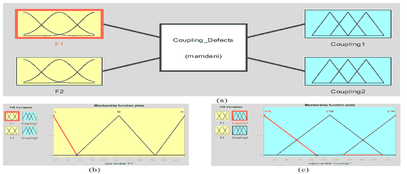
A fuzzy system was designed for couplings of water brake rotor machine for determination its faults that may be appear at any one of them (Rotex & BoWex couplings). The coupling fuzzy system has two inputs and outputs as in Fig. 11(a), the inputs as in Fig. 11(b) are the different frequencies of couplings (F1, and F2). The outputs are the type of fault that can appear at any coupling of water rotor machine (Coupling1, and Coupling2) as shown in Fig. 11(c).
Figure 11: (A) Coupling Fuzzy System, (B) Inputs of Coupling Fuzzy System, (C) Outputs Of Coupling Fuzzy Systems
| Table 8 Levels of Coupling Fuzzy Systems Inputs Values |
|||
|---|---|---|---|
| Input Variables | Low | Medium | High |
| F1 | 15–193 | 188.7– 776.1 | 780.3 – 1394 |
| F2 | 1–2.2 | 1.3 – 3.7 | 2.80 – 5.206 |
| Table 9 Some Of Coupling Fuzzy Systems Rules |
|---|
| Fuzzy Rules (If-Then rules) – relationship between inputs and output |
| If (F1 is H) and (F2 is L) then (Coupling1 is C1H) (Coupling2 is C2L) (1) |
| If (F1 is L) and (F2 is H) then (Coupling1 is C1L) (Coupling2 is C2H) (1) |
| If (F1 is H) and (F2 is H) then (Coupling1 is C1H) (Coupling2 is C2H) (1) |
| If (F1 is H) and (F2 is M) then (Coupling1 is C1H) (Coupling2 is C2M) (1) |
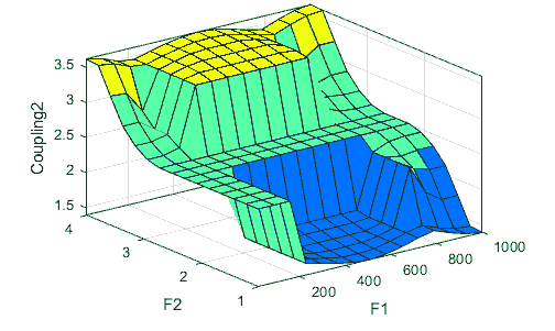
Low, medium, and high frequencies range of coupling fuzzy system inputs are shown in Table 8. If-Then rules were used as a part of proposed fuzzy control or Fuzzy decision step. Table 9 shows some of the fuzzy rules that were implemented in F1 and F2 to determine which coupling has defect. Faults can find in coupling depend on each input’ frequency value. Table 10 and Fig. 12 explained the range of frequencies for each coupling has defect and coupling fuzzy system output, respectively.
| Table 10 Coupling Fuzzy System Inputs and Outputs |
||||
|---|---|---|---|---|
| Variable | Inputs (frequencies value) | Outputs (gear has fault) | ||
| F1 (Hz) | F2 (Hz) | Coupling 1 | Coupling 2 | |
| Values | 952.203 | 1.61 | Coupling 1 has defect | -------- |
| 200.512 | 4.116 | -------- | Coupling 2 has defect | |
Results and Discussion
At the presented work three fuzzy systems were designed and applied for identifying type of faults that appeared in gear box and couplings of water brake rotor machine. Three fuzzy systems for gears, bearings, and couplings faults were implemented. The values of the fuzzy system outputs (values of frequency for each defect) were compared with the measuring values of frequencies of defected components that done by using frequency measuring devices in experiment as shown in Table 11.
| Table 11 Comparison Between The Resulted Values Of Frequency For Each Defect From Measuring Experiment And Fuzzy Systems |
||
|---|---|---|
| Variables | Measuring frequencies (Hz) | Fuzzy systems output |
| Fault of Gear 1 | 606.7 | 575.63 |
| Fault of Gear 2 | 81.9 | 74.113 |
| Fault of Gear 3 | 81.7 | 78.215 |
| Fault of Bearing 1 | 4.223 | 3.17 |
| Fault of Bearing 2 | 120.4 | 127.116 |
| Fault of Bearing 3 | 125.62 | 123.62 |
| Fault of Bearing 4 | 10.86 | 13.801 |
| Fault of Coupling 1 | 980 | 952.203 |
| Fault of Coupling 2 | 4 | 4.116 |
Conclusion
The dynamics of a machine part is investigated. The machine part consists of two gear boxes, motor, and water brake. The identification of fault type process for all components has been implemented, according to the decisions of fuzzy logic control system. Three fuzzy control systems have been designed and applied for gears, bearings, and coupling faults. The results of the proposed fuzzy control system are compared with measured fault frequencies. The comparison illustrated the accuracy of the fuzzy system. The results of the fuzzy system are in good agreement with the measured data. This agreement clarifies the effectiveness of the proposed fuzzy system around fault diagnosis.
Acknowledgement
This research was funded by the Deanship of Scientific Research at Princess Nourah bint Abdulrahman University through the fast-track research funding program. The work reported in this article has been conducted while the researchers are affiliated with Princess Nourah bint Abdulrahman University.
References
Adepoju G, Adeyemi I, Oni O. (2014) Application of fuzzy logic to the speed control of DC Motor. International Journal of Engineering Trends and Technology, 15(5), 215-219.
Adhikari, S., Sinha, N., & Dorendrajit, T. (2016). Fuzzy logic based on line fault detection and classification in transmission line. SpringerPlus, 5, 1002.
Aherwar, A. (2017). An investigation on gearbox fault detection using vibration analysis techniques: A review. Australian Journal of Mechanical Engineering, 10(2), 1-17.
Bediaga, I., Mendizabal, X., Arnaiz, A., & Munoa, J. (2013). Ball bearing damage detection using traditional signal processing algorithms. IEEE Instrumentation & Measurement Magazine, 16(2), 20-25.
Chen, G., & Pham, T.T. (2000). Introduction to fuzzy sets, fuzzy logic, and fuzzy control systems. CRC Press LLC No claim to original U.S. Government works International Standard Book Number 0-8493-1658-8 Library of Congress Card Number 00-045431 Printed in the United States of America.
Chen, Q., Dai, S., & Dai, H. (2019). A rolling bearing fault diagnosis method based on EMD and Quintile Permutation Entropy. Mathematical Problems in Engineering, 2019, 1-8.
Demidova, G.L., Lukichev, D.V., & Denisov, K. (2019). Implementation of type-2 Fuzzy control of PMSM position drive with flexible coupling. 6th International Conference on Control, Decision, and Information Technologies (CoDIT’19): Paris, France.
Espitia, H., Soriano, J., Machón-González, I., & López, H. (2019). Design methodology for the implementation of fuzzy inference systems based on Boolean relations. Electronics, 8(11), 1243.
Gougam, F. (2015). Bearing fault diagnosis based on feature extraction of empirical wavelet transform (EWT) and fuzzy logic system (fls) under variable operating conditions. Journal of vibroengineering, 21, 1636-1650.
Krishnakumari, A., Elayaperumal, A., Saravanan, M., & Arvindan, C. (2017). Fault diagnostics of spur gear using decision tree and fuzzy classifier. The International Journal of Advanced Manufacturing Technology, 89, 3487-3494.
Kumar, S., Lokesha, M., Kumar, K., & Srinivas, K.R. (2018). Vibration based fault diagnosis techniques for rotating mechanical components: Review paper. IOP Conference Series: Materials Science and Engineering, 1-7.
Less, A.W., & Friswell, M.l. (1998). Fault diagnosis of rotating machinery. The Shock and Vibration Digest, 30(1), 4-13.
Lin, T., Yu, K., & Tan, J. (2017). Condition Monitoring and fault diagnosis of roller element bearing. Bearing Technology, P. H. Darji, Ed., INTECH: open access books website.
Milljkovic, D. (2011). Fault detection methods: A literature survey. MIPRO/CTS, 110-115.
Nasiruzzaman, A.B.M. (2010). Using MATLAB to develop standalone graphical user interface (GUI) software packages for educational purposes. Matlab - Modelling, Programming and Simulations, 17- 40.
Ratni, A., Rahmoune, C., & Benazzouz, D. (2017). A new method to enhance of fault detection and diagnosis in gearbox systems. Journal of vibroengineering, 19(1), 176-188.
Sharma, Ph., Sharma, I., Pandiya, D., & Swargari, K.D. (2010). MATLAB/GUI Simulation tool for power system fault analysis with neural network fault classifier. In International Conference on Electrical Power and Energy Systems, ICEPES 2010, MANIT: Bhopal, India.
Sivanandam, S.N., Sumathi, S., & Deepa, S.N. (2007). Introduction to fuzzy logic using MATLAB. Handbook: Springer-Verlag Berlin Heidelberg.
Vicente, S.A., Fujimoto, R.Y., & Padovese, L.R. (2001). Rolling bearing fault diagnostic system using fuzzy logic. IEEE International Conference on Fuzzy Systems, Melbourne, 3(2), 816-819.
Received: 18-Jan-2022, Manuscript No. ASMJ-21-9880; Editor assigned: 20-Jan-2022; PreQC No. ASMJ-21-9880(PQ); Reviewed: 08-Feb-2022, QC No. ASMJ-21-9880; Revised: 12-Feb-2022, Manuscript No. ASMJ-21-9880(R); Published: 18-Feb-2022
